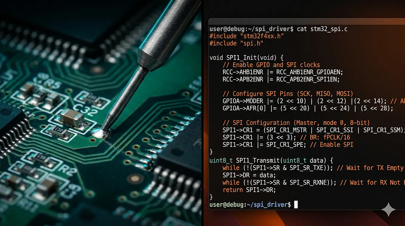
Before You Blame The Hardware (Chip) … Run These
You got the new board and you configured the peripheral. Code looks clean. But nothing happens
Wait… wait … before you start blaming the chip, did you run these 9 checks.
This will take only 20 minutes. But by the end, you’ll know if the bug is in power, decode, timing, or config and what exactly to fix.
The Problem
Bring-up of hardware has one universal frustration:
You write to a register after you read the datasheet
But nothing happens, no output, no error and no clue.
But you see most engineers react badly by doing these things
→ Stare at the datasheet for hours
→ Change random things and hope
But both of these tasks wastes time without any strategy. This is the strategy that actually works.
The 4-Layer DEBUG MODEL
Almost every “nothing happened” issue or if you like to call it a bug lives in one of four layers:
1. Power
2. Decode
3. Timing
4. Configuration
Let us attack them in order and prove each layer before moving to the next.
The 9 Checks
Layer 1: Power & Hardware
Check 1: Power rails
• Is the main power rail operating at specified level ?
• Is the secondary rail present?
• Many chips need VDD and VDDIO
No brainer right. If there is “No power = No chip”.
Hence we are starting here.
Check 2: Decoupling
• Check and see if the capacitors are within millimeters, not inches
• Missing decoupling looks like “bad chip” behavior
• First check the schematic and then check the board.
Layer 2: Address Decode
Check 3: Chip-select polarity
• Check this important thing. Does the device need Active-low vs active-high
• You get this backwards which means the chip will never respond
• Always, I mean always Double-check the datasheet pinout
Check 4: Addressing
• Yes, I hear you. Memory mapped peripheral. Did you check the Base address and is it correct?
• You need to set the bits now right. Of course in the registers. Are all the offsets of those registers correct?
• Which address lines are actually decoded?
Get Embedded System Coach’s stories in your inbox
Join Medium for free to get updates from this writer.
One wrong bit in one of the addresses = wrong chip or wrong register.
Layer 3: Bus Timing
Check 5: R/W and timing
• This is trivial but happens and I saw it. Reading when you meant to write?
• Important things that decide the if controller read the bus transactions, “the setup/hold times”. Are they met?
• Definitely now check the clock polarity. Is it correct?
The bus analyzer doesn’t lie. Your assumptions do.
Check 6: Reset state
• Is the chip or peripherial still in reset?
• Is the enable bit defaulting to “disabled”?
• Many parts boot muted/off for safety
It may happen that the chip isn’t broken. It’s just waiting for permission.
Layer 4: Register Configuration
Now we came to a place where most “silent failures” hide. Let us uncover them.
Check 7: Default register traps
Sound chip sustain = 0?
→ Silence. Even if the note is “on.”
DAC output register = 0?
→ Nothing. Even though you set the waveform.
The chip is working… yes it is but your configuration isn’t.
Check 8: Mode-specific parameters
Square wave needs non-zero pulse width.
→ Zero = DC. Not a wave.
PWM needs period AND duty cycle.
→ Miss one = nothing.
See every mode has required parameters that are to be set, no matter what. Miss one = silence.
Layer 5: Prove IT
Check 9: Prove the write happened
• Sometime you have to rely on the scope and check the bus lines
• Better option, use a logic analyzer on CS/WR/data
• Still not sure if the register is written or not….perform register readback (if supported)
If you can’t prove it happened, you’re just guessing and please stop guessing.
Here is the complete checklist all at one place.
1. Power rails present and correct
2. Decoupling placed close
3. Chip-select polarity matches
4. Addressing correct
5. R/W and timing correct
6. Not stuck in reset/disabled
7. Default register traps checked
8. Mode-specific parameters set
9. Write verified on scope/analyzer
Print this and tape it to your bench.
Having a debugging mindset separates juniors from seniors. Do not be the one who just change things randomly and hope that hardware will work.
Run the checklist in case of hardware not responding. Find the bug. And ship the board. Congratulations.
Did you find this useful. Great. Then bookmark it for your next bring-up.
And of course follow for more embedded systems content.